Tutorial 003: Making Sounds with Buzzer

Electromagnetic BuzzerSo far we’ve used a LED as output to produce light of different colors and intensity (Tutorial 001 and Tutorial 002) but we haven’t generated any sound yet.

In fact that isn’t very difficult to do.

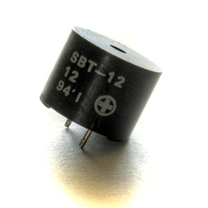
We will use a buzzer for output.

According to Wikipedia … the buzzer or beeper is an audio signalling device, which may be mechanical, electromechanical, or piezoelectric. Typical uses of buzzers and beepers include alarm devices, timers and confirmation of user input such as a mouse click or keystroke.

Tinusaur BuzzerWe will use electromechanical buzzer. When voltage is applied to it its membrane moves up (or down, depending on the particular device) and respectively when there is no voltage the membrane goes back to its normal position. Applying constantly changing voltage will generate audio waves perceived by us as a sound.

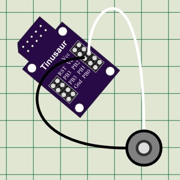
Let’s connect the buzzer to the PB2 of the ATtiny85 on the Tinusaur board.

The program should look very much like the one for blinking LED except that the delay between switching the port should be very short.

In the example below we have a delay 500 and since we’re using the _delay_us() function that means the delay is 500 uS (microseconds). That means the period of the signal will be 2 x 500 uS = 1000 uS (or 0.0001 sec.) and then the frequency is 1 / 0.0001 S = 10000. That means the sound will have frequency of 10 KHz.

Here is the source code:

#include <stdint.h>
#include <avr/io.h>
#include <util/delay.h>
#define BUZZER_PORT     PB2     // Buzzer I/O Port
#define BUZZER_DELAY    500     // Delay for each tick
int main(void)
{
    DDRB |= (1 << BUZZER_PORT); // Set port as output
    while (1) {
        PORTB |= (1 << BUZZER_PORT);
        _delay_us(BUZZER_DELAY);
        PORTB &= ~(1 << BUZZER_PORT);
        _delay_us(BUZZER_DELAY);
    }
    return (0);
}

Full source code with more comments and the other necessary files such as Makefile is available at https://bitbucket.org/tinusaur/tutorials/src/default/tut003_buzzer/

Build the program:

$ make

Upload the code to the controller:

$ avrdude -c usbasp -p t85 -U flash:w:"main.hex":a

The buzzer should start making sound immediately.

Let’s do some more experiments.

Let’s make the delay between the buzzer ticks change over time and see what sound it will produce.

This time instead of _delay_us() we will use the _delay_loop_2() function. According to the _delay_loop_2(int) documentation it produces 4 empty CPU cycles per iteration – in other words with parameter 100 it will produce delay of 400 CPU cycles. That tells us that the maximum is 65536 x 4 = 262252 cycles. That, at 1MHz CPU clock, is approximately 262 mS (milliseconds) maximum delay, … or about 3.8 Hz minimum frequency – perfect for our experiments.

Below is the source code:

#include <stdint.h>
#include <avr/io.h>
#include <util/delay.h>
#define BUZZER_PORT     PB2     // Buzzer I/O Port
#define BUZZER_DELAY    200     // Delay for each tick
int main(void)
{
    DDRB |= (1 << BUZZER_PORT); // Set port as output
    int delay = 0;
    while (1) {
        if (delay < 1) delay = BUZZER_DELAY;
        PORTB |= (1 << BUZZER_PORT);
        _delay_loop_2(delay);
        PORTB &= ~(1 << BUZZER_PORT);
        _delay_loop_2(delay);
        delay--;
    }
    return (0);
}

After building and uploading this should start making sound like of a car alarm.

With similar techniques a lot more complex sounds could be generated.

This post will eventually become Tutorial 003.


OWOWOD – One Wire / One Way Output for Debugging the Tinusaur (Part 3)

tinusaur board schematics owowod

It is time now to write a library that will use the Debugging Output.

In the previous 2 articles about OWOWOD we managed to generate proper serial signal and start sending characters out observing  the result on an oscilloscope.

(see previous articles Part 1 and Part 2 for reference)

The functions we have so far are:

  • void owowod_init(void)
    initializes the output port that will be used for debugging.
  • void owowod_delay(void)
    implements short delay (empty loops) equivalent of one bit transmitted over the wire.
  • void owowod_print_char(uint8_t c)
    output one byte (one character) over the debugging wire.

In order to test those functions we need to connect the generated output serial signal to the computer through a standard serial port – in our particular case that will be a USB to Serial converter. For this we need 2 cables – one for the common ground (usually black in color) and another one for the signal. On the micro-controller side any port that is available for output could be used – PB3 of the ATtiny85 is a good choice to run our tests. The output should be connected to the RxD pin of the USB-to-Serial converter.

Another function that we definitely need is such that can print string of characters. This is pretty simple …

void owowod_print_string(char *s) {
    while (*s) {
        owowod_print_char(*s++);
    }
}

Now we need to run some tests. For that we need a program that will run on the computer and show on the screen the information that comes through the serial port. There are many programs that could be used for that purpose. One particularly simple to use is the Hercules Setup utility by HW group – it is just one EXE file that you run – that’s it.

hercules setup serial

Here are few simple steps to make it work properly:

  • Choose the “Serial” tab.
  • Choose the proper Serial port name, e.g. COM4 – you can obtain that information from Windows Device Manager.
  • Make sure you use the default connection parameters – 9600 bps / 8 bit / no-parity.
  • Open the port to start receiving.

Running the a simple testing program …

#define OWOWOD_PORT PB3
#include "owowod.h"
int main(void)
{
    owowod_init();
    while (1) {
        owowod_print_string("Hello! How are you? Good-bye. :)\n\r");
        _delay_ms(2000);
    }
    return (0);
}

… should output some text on the screen – every 2 seconds.

To make this library more useful we also need a way to print numbers.

Before that we need another function that will convert the value in an integer variable to a string …

#include <stdint.h>

#define USINT2DECASCII_MAX_DIGITS 5

uint8_t usint2decascii(uint16_t num, char* buffer)
{
    const unsigned short powers[] = { 10000u, 1000u, 100u, 10u, 1u };
    char digit;
    uint8_t digits = USINT2DECASCII_MAX_DIGITS - 1;
    for (uint8_t pos = 0; pos < 5; pos++)
    {
        digit = 0;
        while (num >= powers[pos])
        {
            digit++;
            num -= powers[pos];
        }
        if (digits == USINT2DECASCII_MAX_DIGITS - 1)
        {
            if (digit == 0)
            {
                if (pos < USINT2DECASCII_MAX_DIGITS - 1)
                    digit = -16;    // Use: "-16" for space (' ')
            }
            else
            {
                digits = pos;
            }
        }
        buffer[pos] = digit + '0';  // Convert to ASCII
    }
    return digits;
}

The code above was borrowed from another project – LCDDDD – and was slightly modified to fit our needs.

So, we use the usint2decascii function for the function owowod_print_numdec that will print an integer as a decimal number …

void owowod_print_numdec(uint16_t num) {
    char buffer[USINT2DECASCII_MAX_DIGITS + 1];
    buffer[USINT2DECASCII_MAX_DIGITS] = '\0';   // Terminate the string.
    uint8_t digits = usint2decascii(num, buffer);
    owowod_print_string(buffer + digits);
}

Here is an example of how to use the library …

#define OWOWOD_PORT PB3
#include "owowod.h"
int main(void)
{
    owowod_init();
    uint8_t num = 0;
    while (1) {
        owowod_print_numdecp(num);
        owowod_print_char('\n');
        owowod_print_char('\r');
        for (uint8_t i = 0; i < 95; i++) {
            owowod_print_char(' ' + i);
        }
        owowod_print_string("\n\r");
        owowod_print_string("Hello! How are you? Good-bye. :)\n\r");
        owowod_print_string("\n\r");
        _delay_ms(2000);
        num++;
    }
    return (0);
}

This library was developed while working on The Tinusaur but could be used with almost any other ATtiny85 or similar board or system

That’s all. 🙂

PREVIOUS PART 2: OWOWOD – One Wire / One Way Output for Debugging the Tinusaur (Part 2)

PREVIOUS PART 1: OWOWOD – One Wire / One Way Output for Debugging the Tinusaur (Part 1)


All the OWOWOD source code is available at https://bitbucket.org/tinusaur/owowod/src.

The Tinusaur Boards are Back in Stock

Tinusaur Starter KitFinally!

All the parts were received from our suppliers – The Tinusaur Board and The Tinusaur Starter are back in stock at our online store at Storenvy.

We don’t have the resource to supply more that couple of hundred boards at once so if they sold out like the last time please be patient – we will replenish our online store as soon as we can.

The prices, as it is our promise, have not changed since the first batch of boards we shipped. We don’t make profit either. So if you really want to help us keep this project going please consider making a small donation via PayPal.

The First Tinusaur Workshop

The first official Tinusaur workshop took place last Sunday (on the 14th of December) in the Veliko Turnovo University “St. St. Cyril and Methodius”. It was really great!

The workshop was attended by 22 people of age 16 to 44.

The Tinusaur Workshop

As you may have guessed already it was for the absolute beginners so we first learned how to solder basic things like resistors, capacitors and other small parts. Then we move to soldering The Tinusair Board.

The second part was programming the with the “Hello World” of the microcontrollers – a blinking LED.

Not all people who wanted could attend the even so we may organize another one in the first months of the next year.


OWOWOD – One Wire / One Way Output for Debugging the Tinusaur (Part 2)

In my previous post “OWOWOD – One Wire / One Way Output for Debugging the Tinusaur (Part 1)” I wrote how to get a proper reference signal from a serial communication using USB-to-Serial TTL converter.

The Tinusaur BoardThe next steps are to generate the same signal but programmatically using the ATtiny85.

And this is what I did …

I used a ATtiny85 board, the Tinusaur – as you may have guessed already, connected with USBasp programmer to the computer.

The PB0 is used as output but any other available port could be used. That could be done by changing the OWOWOD_PORT in the source code below.

The output is connected to the second digital channel of my DSO Quad oscilloscope.

Here is a fragment of the code that generates the output sugnal …

#define OWOWOD_PORT	PB0	// OWOWOD Port

inline void owowod_init(void) {
	DDRB |= (1 << OWOWOD_PORT);	// Set port as output
	PORTB |= (1 << OWOWOD_PORT);	// Set to HIGH
}

#define OWOWOD_DELAY	23	// Delay for each bit

inline void owowod_delay(void) {
	for (uint8_t i = OWOWOD_DELAY; i != 0; i--) {
		asm volatile ("nop\n\t");
	}
}

void owowod_print_char(uint8_t c) {
	PORTB &= ~(1 << OWOWOD_PORT);	// Set to LOW
	owowod_delay();
	for (uint8_t i = 0; i < 8; i++)
	{
		if (c & 1) {
			PORTB |= (1 << OWOWOD_PORT);	// Set to HIGH
		} else {
			PORTB &= ~(1 << OWOWOD_PORT);	// Set to LOW
		}
		owowod_delay();
		c = (c >> 1);
	}
	PORTB |= (1 << OWOWOD_PORT);	// Set to HIGH
	owowod_delay();
}

int main(void)
{
	owowod_init();
	while (1) {
		owowod_print_char(0x55); // "U"
	}
	return (0);
}

The owowod_init() function sets the port as output and its level to high which is the default for the serial communication.

The owowod_delay() function is a custom delay function that should produce a delay that is equivalent of 1 bit of serial data. This is just an empty loop that I experimentally determined how long it should be.

The owowod_print_char(uint8_t) function outputs one byte of data in serial – starting from the least significant bit of that byte.

To run the test I first started the COMStressTest program and let it output the “U” character (ASCII code in HEX 0x55) indefinitely.

IMPORTANT: All the tests were done with the default settings for the serial COM port which are 9600 bps, 8 bits of data, no parity check and 1 stop bit. This is sometimes denoted as 9600 / 8-N-1 configuration.

Then I ran the C program on the ATtiny.

The graphic on the oscilloscope looked like this …

Serial Debugging Oscilloscope

To get the two signals the same took of course some time to figure out what the timings (the delay between bits) should be.

I am now another step farther.

The next step will be to write a simple debugging library for printing strings and numbers.

PREVIOUS PART: OWOWOD – One Wire / One Way Output for Debugging the Tinusaur (Part 1)

NEXT PART: OWOWOD – One Wire / One Way Output for Debugging the Tinusaur (Part 3)


All the OWOWOD source code is available at https://bitbucket.org/tinusaur/owowod/src.


OWOWOD – One Wire / One Way Output for Debugging the Tinusaur (Part 1)

I always wanted to be able to write something like this in my code

 debugging_print("working, x=%i", x); 

… have that running on the micro-controller and see the debugging output on my computer.

The Problem

Unfortunately that is not easy – in fact not possible with the standard tools used to work with the ATtiny85. The problem is this: (1) those micro-controllers have too few I/O ports; and (2) most of the programmers (the one I’m using is USBasp) do not offer that kind of communication between the micro-controller and the computer, i.e. there is no 2-way communication.

There are many solutions to that problem and while looking on Internet I found this article http://www.ernstc.dk/arduino/tinycom.html that points to some of them:

Since the purpose of The Tinusaur Project is learning I decided to write my own.

USB to Serial TTL
USB to Serial TTL Converter

To do that I needed:

The USB-to-Serial TTL is a device that when connected to the USB port of the computer will look to the operating system like a Serial COM Port. Writing data to that COM port will result in transferring that data through the converter and out to the output pin called TxD – in serial form. It work similarly when receiving data from an external source of signal connected to the RxD pin.

I connected the PB0 of the ATtiny85 to the RxD of the USB-to-Serial TTL and did some experiments. Soon I realized that the timing of the signals was critical for this to work and I needed better way to compose the serial data.

Reference Character Generator

First thing – a serial data character generator that I can use as reference – and what could be better than an original USB-to-Serial converter.

I also needed a software that will generate sequence of test characters that I would use as a test signal. First I though of writing a simple Java program that will send the data to the COM port but then I found an application on Internet that does that already – COMStressTest from AGG Software at http://www.aggsoft.com/com-port-stress-test.htm.

COM Stress Test

I specified my testing data in the “Data source” tab as an external file.

The best testing sequence in this case would be string of “U” characters. This is because the generated signal will consist of equal LOW and HI intervals known also as square wave signal.

 ASCII "U" = 0x55 = 01010101 

To look more precisely at the signal form and parameters I used an oscilloscope – mine is DSO Quad from Seeedstudio at http://www.seeedstudio.com/depot/DSO-Quad-4-Channel-Digital-Storage-Oscilloscope-p-736.html.

The signal should look like this …

Oscilloscope Serial Signal

That’s all for now.

The next step will be to write some code for the ATtiny that will generate the same sequence – all “U” character and try to make it exactly the same as the reference one.

IMPORTANT: All the tests were done with the default settings for the serial COM port which are 9600 bps, 8 bits of data, no parity check and 1 stop bit. This is sometimes denoted as 9600 / 8-N-1 configuration.

NEXT PART: OWOWOD – One Wire / One Way Output for Debugging the Tinusaur (Part 2)


All the OWOWOD source code is available at https://bitbucket.org/tinusaur/owowod/src.