Congratulation and many thanks to all our supporters and friends

Tinusaur Indiegogo campaign 179 percent funded

We are 179% funded! This would’ve not happened without you.

Quick stats:

  • 179% funded on February 20, 2017
  • $4,675 USD total funds raised

We will be posting updates regularly, as often as there’s something to update you about.

All the best,
The Tinusaur Team.

UPDATED: DS1307 Library

The functions were moved to separate files in the DS1307tiny library.

The sample code in the ds1307tiny_test1 module looks cleaner now. The output should be something like this …

DS1307 Serial Real-Time Clock USITWIX ATtiny85

Note that one of the challenges working with a real-time clock the the DS1307 is to set it up with the correct time at the beginning.

  • One way is to do that programmatically – write a program for the microcontroller that will set the clock to specific date & time and run that program right at the specified in the code date & time.
  • Another way of doing taht is to use some sort of USB-to-I2C module and set the date & time from the computer. Such modules exist but they are kind of expensive for the simeple thing they do.
    Ref: http://www.ebay.com/sch/i.html?LH_BIN=1&_nkw=USB+to+I2C&_sop=15

References

Source code available at: https://bitbucket.org/tinusaur/ds1307tiny

More information about the library will be available at its own page: DS1307tiny


Working with DS1307 Real-time Clock and ATtiny85 using USITWIX Library

DS1307 Serial Real-Time Clock USITWIX Tinusaur.

Working with the DS1307 Serial Real-Time Clock using the USITWIX library for I2C / TWI on Atmel ATtiny85 / Tinusaur.

Let’s see how can we work with the DS1307 serial real-time clock using the USITWIX library for I2C / TWI on Atmel ATtiny85 / Tinusaur.

Bellow is the testing setup.

NOTE: We need the USB-to-Serial just for debugging – it isn’t essential part of the setup.

DS1307 Serial Real-Time Clock USITWIX Tinusaur.

There is no library yet to do that but with in the testing code there are few functions that could do the job.

Here is brief a description of the functions:

  • uint8_t ds1307_read_reg8(uint8_t reg_addr) – reads one byte of data from the specified register.
  • uint8_t ds1307_write_reg8(uint8_t reg_addr, uint8_t reg_data) – write one byte of data to the specified register.
  • uint8_t ds1307_init(void) – initializes the circuit by writing specific data into the registers.
  • uint8_t ds1307_setdatetime(uint16_t year, uint8_t month, uint8_t date, uint8_t weekday, uint8_t hour, uint8_t min, uint8_t sec) – sets date and time.
  • uint8_t ds1307_adjust(void) – this is helper function – it sets the date & time to a specific value – let’s not forget that a brand new circuit does not have correct date and time set.

DS1307 Serial Real-Time Clock ModuleThere are 2 additional functions that are used to convert data byte to and from BCD format.

  • static uint8_t bcd2bin (uint8_t val)
  • static uint8_t bin2bcd (uint8_t val)

This is direct link to the source code of the testing program:
https://bitbucket.org/tinusaur/ds1307tiny/src/default/ds1307tiny_test1/main.c

Source code available at: https://bitbucket.org/tinusaur/ds1307tiny

More information about the library will be available at its own page: DS1307tiny

OWOWOD – One Wire / One Way Output for Debugging the Tinusaur (Part 3)

tinusaur board schematics owowod

It is time now to write a library that will use the Debugging Output.

In the previous 2 articles about OWOWOD we managed to generate proper serial signal and start sending characters out observing  the result on an oscilloscope.

(see previous articles Part 1 and Part 2 for reference)

The functions we have so far are:

  • void owowod_init(void)
    initializes the output port that will be used for debugging.
  • void owowod_delay(void)
    implements short delay (empty loops) equivalent of one bit transmitted over the wire.
  • void owowod_print_char(uint8_t c)
    output one byte (one character) over the debugging wire.

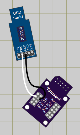
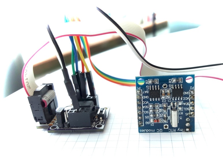
In order to test those functions we need to connect the generated output serial signal to the computer through a standard serial port – in our particular case that will be a USB to Serial converter. For this we need 2 cables – one for the common ground (usually black in color) and another one for the signal. On the micro-controller side any port that is available for output could be used – PB3 of the ATtiny85 is a good choice to run our tests. The output should be connected to the RxD pin of the USB-to-Serial converter.

Another function that we definitely need is such that can print string of characters. This is pretty simple …

void owowod_print_string(char *s) {
    while (*s) {
        owowod_print_char(*s++);
    }
}

Now we need to run some tests. For that we need a program that will run on the computer and show on the screen the information that comes through the serial port. There are many programs that could be used for that purpose. One particularly simple to use is the Hercules Setup utility by HW group – it is just one EXE file that you run – that’s it.

hercules setup serial

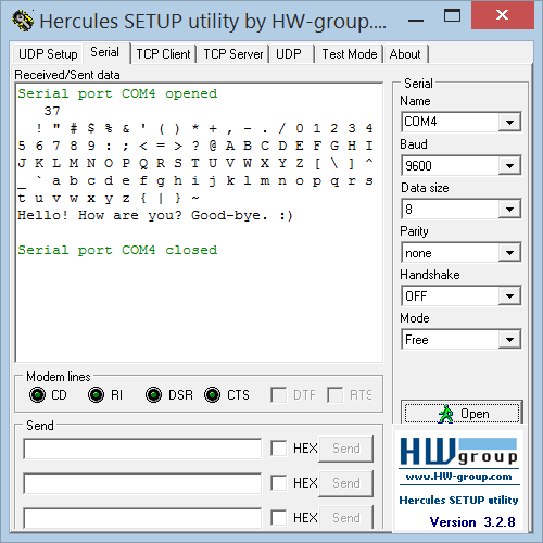
Here are few simple steps to make it work properly:

  • Choose the “Serial” tab.
  • Choose the proper Serial port name, e.g. COM4 – you can obtain that information from Windows Device Manager.
  • Make sure you use the default connection parameters – 9600 bps / 8 bit / no-parity.
  • Open the port to start receiving.

Running the a simple testing program …

#define OWOWOD_PORT PB3
#include "owowod.h"
int main(void)
{
    owowod_init();
    while (1) {
        owowod_print_string("Hello! How are you? Good-bye. :)\n\r");
        _delay_ms(2000);
    }
    return (0);
}

… should output some text on the screen – every 2 seconds.

To make this library more useful we also need a way to print numbers.

Before that we need another function that will convert the value in an integer variable to a string …

#include <stdint.h>

#define USINT2DECASCII_MAX_DIGITS 5

uint8_t usint2decascii(uint16_t num, char* buffer)
{
    const unsigned short powers[] = { 10000u, 1000u, 100u, 10u, 1u };
    char digit;
    uint8_t digits = USINT2DECASCII_MAX_DIGITS - 1;
    for (uint8_t pos = 0; pos < 5; pos++)
    {
        digit = 0;
        while (num >= powers[pos])
        {
            digit++;
            num -= powers[pos];
        }
        if (digits == USINT2DECASCII_MAX_DIGITS - 1)
        {
            if (digit == 0)
            {
                if (pos < USINT2DECASCII_MAX_DIGITS - 1)
                    digit = -16;    // Use: "-16" for space (' ')
            }
            else
            {
                digits = pos;
            }
        }
        buffer[pos] = digit + '0';  // Convert to ASCII
    }
    return digits;
}

The code above was borrowed from another project – LCDDDD – and was slightly modified to fit our needs.

So, we use the usint2decascii function for the function owowod_print_numdec that will print an integer as a decimal number …

void owowod_print_numdec(uint16_t num) {
    char buffer[USINT2DECASCII_MAX_DIGITS + 1];
    buffer[USINT2DECASCII_MAX_DIGITS] = '\0';   // Terminate the string.
    uint8_t digits = usint2decascii(num, buffer);
    owowod_print_string(buffer + digits);
}

Here is an example of how to use the library …

#define OWOWOD_PORT PB3
#include "owowod.h"
int main(void)
{
    owowod_init();
    uint8_t num = 0;
    while (1) {
        owowod_print_numdecp(num);
        owowod_print_char('\n');
        owowod_print_char('\r');
        for (uint8_t i = 0; i < 95; i++) {
            owowod_print_char(' ' + i);
        }
        owowod_print_string("\n\r");
        owowod_print_string("Hello! How are you? Good-bye. :)\n\r");
        owowod_print_string("\n\r");
        _delay_ms(2000);
        num++;
    }
    return (0);
}

This library was developed while working on The Tinusaur but could be used with almost any other ATtiny85 or similar board or system

That’s all. 🙂

PREVIOUS PART 2: OWOWOD – One Wire / One Way Output for Debugging the Tinusaur (Part 2)

PREVIOUS PART 1: OWOWOD – One Wire / One Way Output for Debugging the Tinusaur (Part 1)


All the OWOWOD source code is available at https://bitbucket.org/tinusaur/owowod/src.

OWOWOD – One Wire / One Way Output for Debugging the Tinusaur (Part 1)

I always wanted to be able to write something like this in my code

 debugging_print("working, x=%i", x); 

… have that running on the micro-controller and see the debugging output on my computer.

The Problem

Unfortunately that is not easy – in fact not possible with the standard tools used to work with the ATtiny85. The problem is this: (1) those micro-controllers have too few I/O ports; and (2) most of the programmers (the one I’m using is USBasp) do not offer that kind of communication between the micro-controller and the computer, i.e. there is no 2-way communication.

There are many solutions to that problem and while looking on Internet I found this article http://www.ernstc.dk/arduino/tinycom.html that points to some of them:

Since the purpose of The Tinusaur Project is learning I decided to write my own.

USB to Serial TTL
USB to Serial TTL Converter

To do that I needed:

The USB-to-Serial TTL is a device that when connected to the USB port of the computer will look to the operating system like a Serial COM Port. Writing data to that COM port will result in transferring that data through the converter and out to the output pin called TxD – in serial form. It work similarly when receiving data from an external source of signal connected to the RxD pin.

I connected the PB0 of the ATtiny85 to the RxD of the USB-to-Serial TTL and did some experiments. Soon I realized that the timing of the signals was critical for this to work and I needed better way to compose the serial data.

Reference Character Generator

First thing – a serial data character generator that I can use as reference – and what could be better than an original USB-to-Serial converter.

I also needed a software that will generate sequence of test characters that I would use as a test signal. First I though of writing a simple Java program that will send the data to the COM port but then I found an application on Internet that does that already – COMStressTest from AGG Software at http://www.aggsoft.com/com-port-stress-test.htm.

COM Stress Test

I specified my testing data in the “Data source” tab as an external file.

The best testing sequence in this case would be string of “U” characters. This is because the generated signal will consist of equal LOW and HI intervals known also as square wave signal.

 ASCII "U" = 0x55 = 01010101 

To look more precisely at the signal form and parameters I used an oscilloscope – mine is DSO Quad from Seeedstudio at http://www.seeedstudio.com/depot/DSO-Quad-4-Channel-Digital-Storage-Oscilloscope-p-736.html.

The signal should look like this …

Oscilloscope Serial Signal

That’s all for now.

The next step will be to write some code for the ATtiny that will generate the same sequence – all “U” character and try to make it exactly the same as the reference one.

IMPORTANT: All the tests were done with the default settings for the serial COM port which are 9600 bps, 8 bits of data, no parity check and 1 stop bit. This is sometimes denoted as 9600 / 8-N-1 configuration.

NEXT PART: OWOWOD – One Wire / One Way Output for Debugging the Tinusaur (Part 2)


All the OWOWOD source code is available at https://bitbucket.org/tinusaur/owowod/src.


MAX7219 driver for LED Matrix 8×8

MAX7219LED8x8 is a C library for working with the MAX7219 display driver to control 8×8 LED matrix. It is intended to be used with the Tinusaur board but should also work with any other board based on Atmel ATtiny85 or similar microcontroller.

MAX7219 with LED matrix 8x8

The MAX7219 is manufactured by Maxim Integrated is compact, serial input display driver that could interface microcontrollers to 64 individual LEDs such as 8×8 LED matrix. Only one external resistor is required to set the segment current for all LEDs.

MAX7219 Timing Diagram

To put that in simpler words – with the MAX7219 driver it is possible to control 8×8 LED matrix using just 2 wires serial interface – one for the sync clock and one for the data. There is another wire that could be used to enable/disable the communication with the chip. The maximum frequency for the serial interface is 10MHz.

The LED matrix 8×8 is connected almost diretcly to the MAX7219 driver – only few external components are required.

Working with MAX7219 is very simple – turning on and off individual LEDs is done by sending 2-bytes command to the driver containing the row and the byte which bits define which LED value to set.

There are also few other command that are needed during the initialization process.

The library supports short buffer – only 8 bytes in size – to keep the values before sending them to the driver.

MAX7219LED8x8 is written in plain C and does not require any additional libraries to function except those that come with the WinAVR SDK. Check out the WinAVR – Setup Guide.

Using it is very simple …

    MAX7219_init();
    MAX7219_buffer_set(2, 3); // Set pixel
    MAX7219_buffer_clr(4, 5); // Clear pixel
    MAX7219_buffer_out(); // Output the buffer

Please continue to MAX7219LED8x8 page to see full source code the rest of the article.

External Resources

The source code of the MAX7219LED8x8 library is available at https://bitbucket.org/tinusaur/max7219led8x8

MAX7219 specification and datasheet:

TinuDHT – ATtiny Library for DHT11

Ever wanted to do a project with that cheap DHT11 temperature/humidity sensor and did not want to go the Arduino way but with a simple ATtiny85? You probably know already about  the issues with the existing Arduino based libraries running on the ATtiny microcontrollers, but can’t deal with them. TinuDHT is our answer to this.

TinuDHT is a C library for working with the DHT11 temperature/humidity sensor intended to be used with the Tinusaur but should also work with any other board based on ATtiny85 or similar microcontroller.

DHT11

The DHT11 is very basic, low-cost digital temperature and humidity sensor. It uses a capacitive humidity sensor and a thermistor for measurements, and sends out the info to the data pin. It is relatively simple to use it, but requires precise timing to retrieve the data correctly. One disadvantage of this sensor is that you can get new data from it no more often than once every 1 or 2 seconds.

The primary problem with the direct use of the Arduino libraries is that the ATtiny85 and Tinusaur in particular do not have enough resource to handle the send/receive process properly, i.e. not enough CPU power, in result of which the timing of the signals that are sent to the sensor and received from it become messed up. In addition those libraries use Arduino specific code and/or C++ specific syntax which makes them incompatible with the plain C language.

TinuDHT library is based on DHT11Lib code. It was adapted for ATtiny, removed Arduino dependencies and timing was adjusted to work well on ATtiny85 at 1 MHz. There are few other changes and optimizations for speed and size.

TinuDHT is written in plain C and does not require any additional libraries to function except those that come with the WinAVR SDK. Check out the WinAVR – Setup Guide.

Please go to TinuDHT page to see the full document.

The source code of the TinuDHT library is available at https://bitbucket.org/tinusaur/tinudht.

Tinusaur Board DHT11 LCD Battery