How to Setup the Arduino IDE to Work with the Tinusaur Boards

Arduino IDE for Tinusaur Boards

UPDATE: There is an updated version of the Arduino Setup Guide at our new website https://tinusaur.com/guides/arduino-ide-tinusaur-setup/

This is a short guide how to setup the Arduino IDE to work with the Tinusaur boards.

What it does basically is to make it work with the Atmel ATtiny85/45/25 microcontrollers. The only difference is that it will appear on the list of boards as Tinusaur – this is done for convenience, so relatively inexperienced people won’t get confused by the long list of unknown boards and microcontrollers.

Installing the Arduino IDE

First of all, we need the Arduino IDE itself. It could be downloaded from https://www.arduino.cc/en/Main/Software – the official Arduino website. The current version at the time of writing this guide was 1.6.8 but should work with all the most recent versions.

Start the Arduino IDE first.


Adding Support for the Tinusaur Boards

Go to the menu File / Preferences.

Find the “Additional Boards manager URLs” and the button on the right that will open an edit box.

Put the following URL in the edit box:

https://bitbucket.org/tinusaur/arduino-ide-boards/raw/default/package_tinusaur_attiny_index.json

NOTE: It is possible to have multiple URLs as long as they are put on separate lines.

Close the edit dialog by pressing “OK”. Close the “Preferences” dialog by pressing “OK”.

Go to the menu Tools / Board:… / Boards Manager.

This will open an additional dialog window with boards information.

You may need to wait until all data is loaded.

From the drop-down menu “Type” choose the “Contributed” item.

Locate the “Tinusaur Boards” item and click on it.

Press the “Install” button. That will install the necessary files into the Arduino IDE.

Close the dialog by pressing the “Close” button.

Setup to use the Tinusaur Board

Go to menu Tools / Board:…

The Tinusaur should be available somewhere at the bottom of the list. Choose the Tinusaur.

It is important to setup the other parameters for the board.

Go to menu Tools / Processor:… and choose the appropriate CPU type. If unsure choose ATtiny85.

Go to menu Tools / Clock:… and choose the appropriate CPU frequency. If unsure choose 1 MHz.

Go to menu Tools / Programmer:… and choose the appropriate programmer. If unsure choose USBasp.

That’s it.

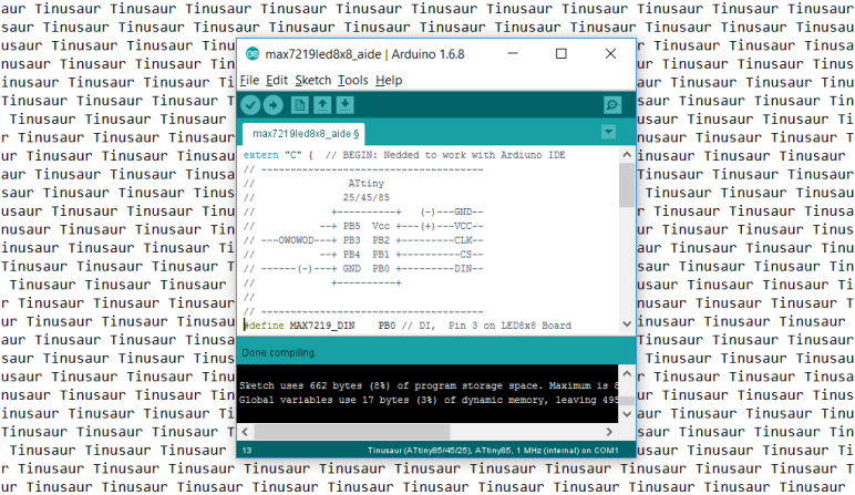
Another version of this guide but with screenshots is available at the Arduino IDE Setup page.

ATtiny85 and ESP8266 – do you really need that?

Tinusaur ATtiny85 ESP6288 Shield

Yes, why not. And here is what I did …

(this will be series of posts about what I did with ATtiny85/Tinusaur and ESP8266 WiFi module)

First, what could be accomplished with such limited device as ATtiny85? It has 8 pins, 2 of which are for the power (Vcc and GND), one for the RESET (pin 1 – PB5), another one potentially for the OWOWOD debugging (pin 2 – PB3) through serial line, so there are 4 pins left: PB0, PB1, PB2, PB4.

ATtiny85 pinout

ESP8266 module uses UART to communicate so it would require at least 2 pins to work – URxD and UTxD.

There is also CH_PD pin that controls the chip and could power it down.

ESP8266 module pinout

At first it may look that this takes another 3 pins out but not really.

If we use the CH_PD to disconnect the ESP8266 module we can use the same pins for other purposes like connecting additional I²C devices to the micro-controller. This is what I did.

What are the challenges?

1) There’s no UART on ATtiny85 so I had to write my own that takes advantage on the built-in USI unit. The library is called USIUARTX and will be presented in another blog post. The source code will be uploaded at https://bitbucket.org/tinusaur/ very soon.

2) There’s no I2C on ATtiny85, not even the TWI (Two Wire Interface, basically I2C) that some other Atmel chis have, so I had to write my own that takes advantage on the built-in USI unit. The library is called USITWIX and will be presented in another blog post. The source code is already available at https://bitbucket.org/tinusaur/usitwix. The BMP180TINY library (Source code at https://bitbucket.org/tinusaur/bmp180tiny) uses it to communicate with an BMP180 pressure sensor.

That’s it for now.

My next post will be about the above mentioned libraries.

The OWOWOD Library

OWOWOD is One Wire / One Way Output for Debugging library. It allows you to output text from the Tinusaur (ATtiny85 microcontroller or other similar), though USB-to-Serial or TTL converter (based on PL2303, CH340G or similar) and to the computer screen using COM port monitoring tool.

Why one would need something like that?

I would’ve been nice if it was possible to write something li this …

debugging_print("working, x=%i", x);

… and see the output on a computer. Great for debugging and other things.

Unfortunately there is no easy way of doing that – in fact not possible with the standard tools used to work with the ATtiny85. The problem is this: (1) those micro-controllers have too few I/O ports; and (2) most of the programmers (ex.: USBasp) do not offer that kind of communication between the micro-controller and the computer, i.e. there is no 2-way communication.

USB to Serial TTL

There are some solution and the OWOWOD library is just one of them. It uses an additional hardware component – USB-to-Serial converter also known as USB TTL Converter. They are very inexpensive, easy to find and work with.

The OWOWOD Library could do that.

Tinusaur connected to USB-to-Serial PL2303 using OWOWOD
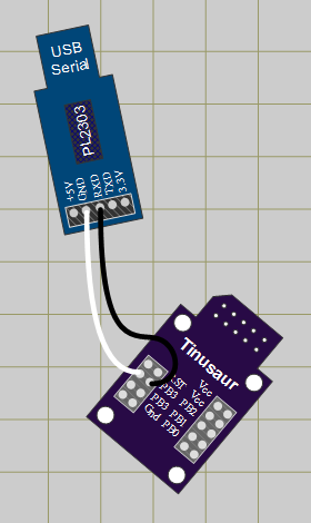
For this to work we need …

  • Micro-controller
  • USB-to-Serial converter
  • Computer

The Library works like this …

  • When you use a library function like owowod_print_char(‘U’) it will start sending sending the bits of the ‘U’ byte (hex: 0x55, bin: 01010101) in series, i.e. one bit after another, through one of the microcontroller pins – for instance PB3.
  • At the other end of the wire there is USB-to-Serial converter that will take the individual 01010101 bits and re-compose them back into one byte as 0x55.
  • Then the USB-to-Serial converter will send that ‘U’ byte (0x55) to the computer USB port.
  • The computer sees the USB-to-Serial as a Serial COM Port port, so it reads that ‘U’ byte.
  • Using another program on the computer we get that ‘U’ byte and show it on the screen.

It works similarly for whole strings and other data.

Let’s take a look at some usage examples:

#include <stdlib.h>
#include <avr/io.h>
#define OWOWOD_PORT PB3
#include "../owowod/owowod.h"
int main(void) {
    owowod_init();
    owowod_print_char('U');
    owowod_print_string("Hello!\r\n");
    owowod_print_numdec(1);
    owowod_print_numdecp(2);
    owowod_print_numdecu(123);
    owowod_print_numdecup(456);
    return 0;
}

Always initialize with owowod_init() function.

You can print char, string but also decimal signed and unsigned integer numbers.

The decimal numbers are 16-bit integers.

The owowod_print_numdecp() and owowod_print_numdecup() functions print left padded numbers – that means there will be some spaces on the left as if the numbers are right aligned. Like this …

    12
   345
 67890
    -2
   -34
-56789

Because this would be used for debugging in most of the cases there are some helpful definitions for that purpose in the “debugging.h” file.

Here is an example of how to use it …

#define F_CPU 1000000UL
#include <stdint.h>
#include <avr/io.h>
#define OWOWOD_PORT PB3
#include "../owowod/owowod.h"
#include "../owowod/debugging.h"
int main(void) {
    DEBUGGING_INIT();
    DEBUGGING_NUMDEC(-123);
    DEBUGGING_NUMDECP(-4567);
    DEBUGGING_NUMDECU(123);
    DEBUGGING_NUMDECUP(4567);
    DEBUGGING_STRING("Hello!");
    DEBUGGING_STRINGLN("Hi!");
    DEBUGGING_VAR("X", 1);
    DEBUGGING_VARU("Y", 23);
    DEBUGGING_ERROR(4, "Connect");
    return 0;
}

DEBUGGING_STRINGLN adds CRLF new line at the end.

DEBUGGING_VAR and DEBUGGING_VARU print variable name and then the value.

DEBUGGING_ERROR prints the error code then the message.

hercules setup serial

To see the results we need a program that will run on a computer and show on the screen the information that comes through the serial port. There are many programs that could do that. One particularly simple to use is the Hercules Setup utility by HW group – it is just one EXE file that you run – that’s it.

The OWOWOD has its own page, it is at:
http://tinusaur.org/projects/owowod/

This library was developed with and tested on the following microcontrollers: ATtiny85, ATtiny45, ATtiny25 but should also work on other tinyAVR chips.

The library was tested to work with following USB-to-Serial converters: PL2303, CH340G.

Source code is available at https://bitbucket.org/tinusaur/owowod.

References

There are many project in the Internet that solve the same or similar problems and this article http://www.ernstc.dk/arduino/tinycom.html that points to some of them:

On eBay: USB to Serial TTL converter – to transfer the debugging output from the ATtiny micro-controller to the computer.

Here are links to some of the posts related to this library:


Printing Decimal Numbers on SSD1306 OLED Display Using the SSD1306xLED Library

Tinusaur SSD1306XLED SSD1306 OLED Llibary

UPDATE: Please, check the most recent post about this library at https://tinusaur.org/tag/ssd1306xled

After playing for awhile with that SSD1306 OLED display I decided to add few more things to the SSD1306xLED library and the ability to print numbers seamed to be an important one.

Tinusaur SSD1306xLED ATtiny85 SSD1306 OLDEThere is already a function in the library that outputs strings so I needed only the conversion from int to a decimal string. So I used another function usint2decascii that I previously wrote for another project OWOWOD which code, in turn, I borrowed from a third project LCDDDD – an LCD Direct Drawing Driver for PCD8544 based displays such as Nokia 3310 LCD. The weird LCDDDD name comes from the fact that it outputs the data directly to the LCD instead of storing it into a buffer first and then periodically outputting it to the LCD – this is unlike most of the popular LCD drivers.

Here is the main function definition …

uint8_t usint2decascii(uint16_t num, char* buffer)

The function requires a small buffer to store the result. Since the largest number is 65535 – that is 0xFFFF in hex, 5+1 bytes are needed for that buffer.

For convenience, there are 2 functions for direct printing of numbers. Below is their implementation – it’s very simple:

#define USINT2DECASCII_MAX_DIGITS 5

char ssd1306_numdec_buffer[USINT2DECASCII_MAX_DIGITS + 1];

void ssd1306_numdec_font6x8(uint16_t num) {
  ssd1306_numdec_buffer[USINT2DECASCII_MAX_DIGITS] = '\0';
  uint8_t digits = usint2decascii(num, ssd1306_numdec_buffer);
  ssd1306_string_font6x8(ssd1306_numdec_buffer + digits);
}

void ssd1306_numdecp_font6x8(uint16_t num) {
  ssd1306_numdec_buffer[USINT2DECASCII_MAX_DIGITS] = '\0';
  usint2decascii(num, ssd1306_numdec_buffer);
  ssd1306_string_font6x8(ssd1306_numdec_buffer);
}

The ssd1306_numdec_font6x8 only prints the number while ssd1306_numdecp_font6x8 prints numbers the same way but right-aligned and 5-digit padded.

Printing numbers is as simple as this …

  ssd1306_setpos(20, 4);
  ssd1306_numdecp_font6x8(12345);

Here is a little more complicated example …

ssd1306_setpos(40, 3);
ssd1306_string_font6x8("a=");
ssd1306_numdecp_font6x8(0xFA32); // dec: 64050
ssd1306_setpos(40, 4);
ssd1306_string_font6x8("b=");
ssd1306_numdecp_font6x8(0x05CD); // dec: 1485

ssd1306xled sample screen

It prints “a=”, “b=” and then their values. Both numbers are right-aligned and left-padded with up to 4 spaces.

The latest test program in SSD1306xLED includes examples of how to use the ssd1306_numdec_font6x8 and the ssd1306_numdecp_font6x8 functions.

The SSD1306xLED library is at SSD1306xLED page.

The source code of the SSD1306xLED is available at https://bitbucket.org/tinusaur/ssd1306xled

The source code of the TinyAVRLib is available at https://bitbucket.org/tinusaur/tinyavrlib

MAX7219 driver for LED Matrix 8×8

MAX7219LED8x8 is a C library for working with the MAX7219 display driver to control 8×8 LED matrix. It is intended to be used with the Tinusaur board but should also work with any other board based on Atmel ATtiny85 or similar microcontroller.

MAX7219 with LED matrix 8x8

The MAX7219 is manufactured by Maxim Integrated is compact, serial input display driver that could interface microcontrollers to 64 individual LEDs such as 8×8 LED matrix. Only one external resistor is required to set the segment current for all LEDs.

MAX7219 Timing Diagram

To put that in simpler words – with the MAX7219 driver it is possible to control 8×8 LED matrix using just 2 wires serial interface – one for the sync clock and one for the data. There is another wire that could be used to enable/disable the communication with the chip. The maximum frequency for the serial interface is 10MHz.

The LED matrix 8×8 is connected almost diretcly to the MAX7219 driver – only few external components are required.

Working with MAX7219 is very simple – turning on and off individual LEDs is done by sending 2-bytes command to the driver containing the row and the byte which bits define which LED value to set.

There are also few other command that are needed during the initialization process.

The library supports short buffer – only 8 bytes in size – to keep the values before sending them to the driver.

MAX7219LED8x8 is written in plain C and does not require any additional libraries to function except those that come with the WinAVR SDK. Check out the WinAVR – Setup Guide.

Using it is very simple …

    MAX7219_init();
    MAX7219_buffer_set(2, 3); // Set pixel
    MAX7219_buffer_clr(4, 5); // Clear pixel
    MAX7219_buffer_out(); // Output the buffer

Please continue to MAX7219LED8x8 page to see full source code the rest of the article.

External Resources

The source code of the MAX7219LED8x8 library is available at https://bitbucket.org/tinusaur/max7219led8x8

MAX7219 specification and datasheet:

TinuDHT – ATtiny Library for DHT11

Ever wanted to do a project with that cheap DHT11 temperature/humidity sensor and did not want to go the Arduino way but with a simple ATtiny85? You probably know already about  the issues with the existing Arduino based libraries running on the ATtiny microcontrollers, but can’t deal with them. TinuDHT is our answer to this.

TinuDHT is a C library for working with the DHT11 temperature/humidity sensor intended to be used with the Tinusaur but should also work with any other board based on ATtiny85 or similar microcontroller.

DHT11

The DHT11 is very basic, low-cost digital temperature and humidity sensor. It uses a capacitive humidity sensor and a thermistor for measurements, and sends out the info to the data pin. It is relatively simple to use it, but requires precise timing to retrieve the data correctly. One disadvantage of this sensor is that you can get new data from it no more often than once every 1 or 2 seconds.

The primary problem with the direct use of the Arduino libraries is that the ATtiny85 and Tinusaur in particular do not have enough resource to handle the send/receive process properly, i.e. not enough CPU power, in result of which the timing of the signals that are sent to the sensor and received from it become messed up. In addition those libraries use Arduino specific code and/or C++ specific syntax which makes them incompatible with the plain C language.

TinuDHT library is based on DHT11Lib code. It was adapted for ATtiny, removed Arduino dependencies and timing was adjusted to work well on ATtiny85 at 1 MHz. There are few other changes and optimizations for speed and size.

TinuDHT is written in plain C and does not require any additional libraries to function except those that come with the WinAVR SDK. Check out the WinAVR – Setup Guide.

Please go to TinuDHT page to see the full document.

The source code of the TinuDHT library is available at https://bitbucket.org/tinusaur/tinudht.

Tinusaur Board DHT11 LCD Battery

Tutorial 002: Fading LED x1

UPDATE: 2022
WINAVR is (or was) a great project. Its most “recent” package is from 2010-01-20. In other words, it is outdated. There are many projects that attempted to replace it but none of them (AFAIK) is extremely popular. We’ve put together a very detailed guide on how to setup everything manually – AVR GCC Toolchain – Setup for Windows.

Another beginners tutorial is on the way – this time about a fading in and out LED.

This is simple tutorial that shows how to connect a LED to the ATtiny85 based Tinusaur board and write a program that makes the LED to fade in and out using PWM (pulse-width-modulation) technique.

PWM Diagram

Note: The code in this tutorial does not use the built-in PWM capabilities of the ATtiny microcontrollers, instead it uses direct bit manipulation since this un easier way to understand how it works. Another tutorial should cover the PWM functionality that is built into the microcontroller.

Tinusaur Board with LED

The Tinusaur board is a standard ATtiny breakout board so this could be applied to almost any other board that has ATtiny microcontroller on it. The code was tested to work with ATtiny13, ATtiny25, ATtiny45 and ATtiny85 but will probably work on any other ATtiny microcontrollers as well.

Please go to Tutorial 002: Fading LED x1 to see the full document.

You can also check the Tinusaur Board – Assembling Guide and the WinAVR – Setup Guide.

WinAVR – Setup Guide

UPDATE: 2022
WINAVR is (or was) a great project. Its most “recent” package is from 2010-01-20. In other words, it is outdated. There are many projects that attempted to replace it but none of them (AFAIK) is extremely popular. We’ve put together a very detailed guide on how to setup everything manually – AVR GCC Toolchain – Setup for Windows.

WinAVR is a great tool to do development for Atmel AVR micro-controllers on the Microsoft Windows platform. It consists of all the necessary C/C++ compiler, linkers and other GCC tools that you need to write, build and program those micro-controllers.

WinAVR: http://winavr.sourceforge.net

WinAVR
WinAVR (pronounced “whenever”) is a suite of executable, open source software development tools for the Atmel AVR series of RISC microprocessors hosted on the Windows platform. It includes the GNU GCC compiler for C and C++.

Here we have put together a very short guide on how to setup and use WinAVR for programming the Attiny85 micro-controller and the Tinusaur Board in particular.

The guide was tested mostly under Microsoft Windows 8.1 operating system.

The example source code was tested on ATtiny85 microcontroller installed on a Tinusaur project boards and programmed using USBasp ISP programmer.

Please go to WinAVR – Setup Guide page to read the entire document.

Assembling Guide

This a short guide about how to assemble the Tinusaur Board.

Tinusaur Board

The Tinusaur Board is what the Tinusaur project is built around. It is rather simple PCB with a dozen components on it.

The board is easy to assemble and does not require very special skills or instruments.

IMPORTANT: If you are uncertain about anything please consult with our website, community or someone more knowledgeable in the subject.

Tinusaur PCB design and layout

There are 4 areas that the Tinusaur board could be divided to: A1, A2, A3, A4.

Assembling

Here is the recommended order of soldering the parts:

  1. MCU socket. Note: do not insert the chip yet.
  2. Capacitors C1, C2 and resistor R1.
  3. Headers H1, H2.
  4. External power header – red.
    Battery on/off header – yellow.
  5. ISP header.
  6. Battery holder.
  7. RESET button.

The battery holder and the battery are optional but if you decided to put them on make sure you solder the battery holder before the RESET button.

IMPORTANT:

External power header (JP1, red, the one closer to the 8-pin header H1) is to connect external power. DO NOT put a jumper there – that could damage the board.

Battery On/Of header (JP2, yellow, the one closer to the mount hole) is to connect/disconnect battery to/from the board. DO NOT have this on while the board is connected to the programmer or external power source – there is no circuit to protect the battery from overcharging.

If you’re not going to use an external power source or the battery on the board don’t put any jumper on at all.

Tinusaur Schematics

Board Components

Name

Description

PCB

Tinusaur Board

MCU, Attiny85

Atmel AVR ATtiny85 microcontroller

Socket, DIP-8

DIP-8 socket for MCU

H1, Header

Header 2×4, Female

H2, Header

Header 2×5, Female

ISP, Header

Header 2×5, Male, for ISP

RESET, Button

Tactile push button, for RESET

Power, Header

Header 1×2, Male, red – external power

Battery, Header

Header 1×2, Male, yellow – battery power on/off

Battery, Jumper

Jumper, 2-pin, yellow – for battery power on/off

C1, Capacitor

Capacitor 100uF, Low profile 5×5 mm

C2, Capacitor

Capacitor 100nF, Small

R1, Resistor

Resistor 10K, Small, 1/8W

Battery holder

Battery holder for CR2032

Battery 3V

Battery 3V, CR2032

Note (about external power source): If you’re going to use external power source (JP1, red in color, the one close to the 8-pin header H1) make sure you connect the negative pole (-) to the outer pin of the header and positive (+) to the inner one.

Note (about battery placement): If you’re going to use the battery in the holder make sure you insert it correctly – that is to have the negative (-) downwards (facing the holder) and the positive (+) (the side with the text markings) upwards.


This guide as well as other documents are available as PDF at the Guides page. Please note that any updates will be posted there.

Pros and Cons

Tinusaur PCB design and layoutIs there anything special about this board? No! Absolutely nothing.

Even though the Tinusaur is a very simple thing it has its advantages as well as disadvantages that need to be addressed.

It is a platform that is simple and easy to understand for everyone – perfect for a quick start and in learning how to create things.

The board consists of the minimum required components for its micro-controller to function properly. There are no missing parts that could save on space and cost but may impact stability. There are no extra components that you may not always need.

  • There are benefits of choosing the Tinusaur over some other similar projects.
  • There are of course things that are not perfect with the Tinusaur and we must mention them a.

Still interested …

More details are laid out in the Pros and Cons page.