We received some emails asking if we could offer the boards and the parts for purchasing … so we did it. We have to admit that it took us some time to arrange everything but some of the circumstances were beyond our control.
At the moment we have only one product listed – that’s the Tinusaur Starter.
We have put up for sale very small batch of those starter kits as we don’t know what the interest will be. Please note that at the moment we don’t do this as a business and we do not make any profit – the sale only covers our expenses.
IMPORTANT: This is offered as a kit which means that you have to assemble it yourself.
We chose Storenvy for our shopping site and we think that it was a good choice – it’s easy to setup and use but also provides all the functionality that we need at this stage. You can pay for your orders with PayPal.
We have a shield-like proto board now, very preliminary design. It will allow you to solder some components on it and then put it on top of the Tinusaur Board – very much like any other shield-like board. It is available on OSHPark at this address: https://oshpark.com/shared_projects/2zuAJJGZ.
All the parts for the Tinusaur Starter kit were ordered from our suppliers. We hope everything to be in our office (most of them already arrived) by the end of the month. Will post more information about it here and on our Twitter/Facebook/etc.
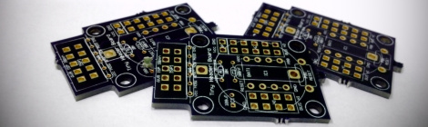
The boards for the Tinusaur Starter were ordered from OSHPark – great quality, no doubt. We also ordered some boards from Seeed Studio to see how’s their quality.
As follow up to our first Tutorial 001 we are planing to put another one – Tutorial 002, probably about how to connect a push-button to the board and receive input from it.
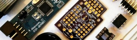
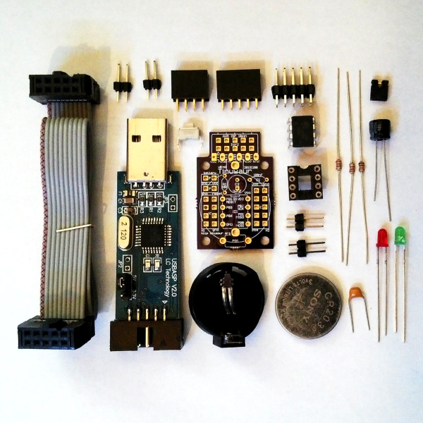
To start making things with the Tinusaur you need the board, the parts, a programmer with a cable and couple of LEDs to make your first blinking lights program for ATtiny85 microcontroller.
We’re ordering the PCBs and the parts from the manufacturers and it seems that the total cost for the full package will be 8 to 9 USD. Once we have everything here we’ll run a small test sale to see what’s the interest in the kit. The estimated cost for delivery of the kit to any country in the world is about 2 USD. So the total cost to get it would be 10 to 11 USD – very affordable for everyone.
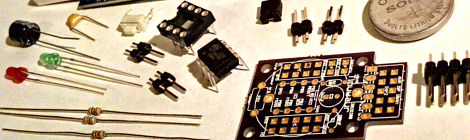
Here is a list of everything that will be included in the Tinusaur Starter:
This is very simple tutorial how to make a LED blinking.
Since the Tinusaur board is a very standard ATtiny breakout board this could be applied to almost any such other board.
The code was tested to work with ATtiny13, ATtiny25, ATtiny45 and ATtiny85 but will probably work other chips too.
We assume that the Tinusaur board is already assembled, successfully; connected through the ISP programmer to the computer; and development environment . It is not the subject of this tutorial how to assemble the board or how to setup development environment.
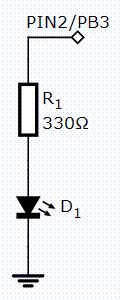
The LED should be connected on pin 2 of the ATtiny – this is PB3 – through a resistor, and to the GND.
The LED, marked as D1, is just a standard light emitting diode.
Set the LED wire signal to “1” – that will make it to light.
Wait a little – 200 milliseconds.
Clear the LED wire signal to “0” – that will turn it off.
Wait a little -400 milliseconds.
Do it again.
Here is the entire source code:
/**
 * The Tinusaur Project
 *
 * Tutorial 001: Blinking LED
 *
 * file: main.c
 * created: 2014-01-04
 *
 **/

#include <avr/io.h>
#include <util/delay.h>

// ====================================
//                ATtiny
//               25/45/85
//              +--------+
//            --+ o  Vcc +------------
//  LED - PB3 --+        +--
//            --+        +--
//  ------------+ GND    +--
//              +--------+
// ====================================

// Define the I/O port to be used for the LED.
// This a number between 0 and 7 that tells which bit to use.
#define LED_PORT PB3

int main(void) {

	// Set the LED port number as output.
	// The DDRB is the data direction for port B.
	// This ...
	//  - shifts the "1" on left to the desired position and ...
	//  - does bitwise "OR" with the value in the port register.
	DDRB |= (1 << LED_PORT);

	// Start infinite loop.
	// (this is how most programs work)
	while (1) {

		// Set the LED bit to "1" - LED will be "on".
		PORTB |= (1 << LED_PORT);

		// Wait a little.
		// The delay function simply does N-number of "empty" loops.
		_delay_ms(200);

		// Set the LED bit to "0" - LED will be "off".
		PORTB &= ~(1 << LED_PORT);

		// Wait a little.
		_delay_ms(400);

		// Do it again ...
	}

	// Return the mandatory for the "main" function value.
	return (0);
}
In this post are discussed some of principals used while designing this board.
Size and form factor
The goal of making this board is not to have a smaller or the smallest PCB that runs on ATtiny. The goal is to have a board that could be used for prototyping simple projects as well as fitting reasonable small (or large, depending on the view) circuits on an additional shield board.
Headers
There are 2 header – one 2×4 – H1 and another one 2×5 – H2.
The idea is that all the outer pins are GND while all the inner pins are connected directly to the MCU. The longer header H2 has its top-left pin connected to the Vcc like the 2nd-row one on the left. That gives us one more power source wire.
MCU
This board could work with the smaller Atmel AVR ATtiny controllers such as ATtiny 25/45/85, ATtiny13 as well as most of their variations – as long as they are in DIP-8 case.
Programming
The programming is done through the standard 10-pin ISP connector using any compatible AVR ISP programmer. On the diagram below it is marked as PC.
The connector is placed on the board in such a way so it could be chopped off if not needed and make the board little smaller. The programming probe, marked as PP on the diagram below, has holes that could help in the cutting. In case you need to connect the board to a programmer again at later time you can solder some wires to what’s left of the probe.
Board
Technical parameters: 2 layer board of 0.90×1.40 inches (22.96×35.66 mm).
There are 4 mounting holes marked as MH on the diagram below.
Power
During the development the board could be powered through the ISP programmer.
External power source could be connected to the board through a jumper marked as PS on the diagram below.
There is an optional button-cell battery mount on the back of the board, marked as BM on the diagram below. The battery could be switched on and off using the jumper that is marked as BS on the diagram.
Areas
There are 4 areas that a Tinusaur board could be divided to: A1, A2, A3, A4. That is applicable for the actual Tinusaur main board as well as any shield boards one could produce.
A1, the bottom part of the board:
this is the area where the RESET button is placed on the main board.
for a shield board that area could be used to put some components and produce a simple circuit.
A2, the mid of the board – heads:
there are 2 header – one 2×4 and another one 2×5, they are different for a reason.
on the main board, between the headers, is placed the MCU.
on a shield board, between the headers, could placed a 8-pin chip or other components.
A3, the top part of the board:
there are the minimum required components for the MSU to work – 2 capacitors for the power source and one pull-up resistor for the RESET.
jumper for external power.
jumper to switch on/off battery.
A4, tip of the board:
standard ISP programming connector.
Additionally …
A5, the other side of the board:
there is optional cell-button battery mount.
Tinusaur Reference DesignTinusaur Proto v0.1 m2 – Schematics
The new prototype PCBs just arrived from OSHPark – great quality as usual.
I noticed that there are only few things that I may change before call it official: slightly move some components around so they fit better and become easier to solder; add one jumper for switch on/off the optional button cell battery on the bottom of the board; make some pads and holes larger; … and few other things.
First I made a testing chassis for the vibrating motors. As it is seen on the picture they are wired (connected with thin copper cable) to a battery – this allowed me to make some experiments before deciding how to put them on the final version of the board. It turned out that they should be in angle. I decided to put them in 90 degree.
So, I made another chassis with the 2 motors positioned in 90 degrees (2 x 40 degrees)
I used double-sided prototyping board and the motors’ contacts fitted nicely into the holes, no soldering was necessary – I just fixed them to the board with isolated wires.
On the top of the chassis I tied a shield-like board that connects motors to the MCU board. Later I may need to add some components on that shield board, like driver for motors, sensors, etc.
For the “brain” of this bug I used one of the prototype boards of the Tinusaur based on Atmel AVR ATtiny25, coupled with a 2xAAA package for batteries.
At the moment the motors are connected directly to the output pins of the MCU, there are no any drivers. It works fine for now but may need to change.
The code for this experimental build is very simple – it just turns on and off 2 output pins on the MCU.
The 2 vibrating motors, even though I bought them together, do not work the same way. That creates some difficulties controlling the direction of the bot – it turns well in one direction but not that well in the other. There are even bugger problems moving forward.
In the next version I should definitely make changes in the vibrating motors – use some of those button-like ones and also change their angle. A friend of mine suggested that I should probably play more with the “legs” as they are crucial for the movements with which I agree.
The battery is too big, but button cell battery is not enough to power the MCU and the motors for a long time, so I should probably think of another power source.
There is a short video on YouTube that shows more photos of how I built this with some footage at the end of the robot moving around.
Any comments and suggestions are really appreciated.
I have finally managed to finish the first version of the schematics and PCB‘s and to order the first 3 pieces. This work is based on some previous experiments and designs.
Schematics
The schematics is nothing special – it is the well known minimal configuration for the ATtiny plus just few addition components – some of them optional.
The required components are the 2 capacitors between Vcc/GND and the 10K resistor on the RESET wire.
There is RESET push-button connected to the micro-controller.
The micro-controller connects to the outside world through 2 headers – H1 an H2. They are in two different sizes for number of rasons: first – to have more connections available for wires, and second – to make sure we won’t mistake H1 and H2.
Next to the headers there is 1×2 connector for external power source.
There is an optional battery for application where built-in power source is needed.
PCB
The PCB is a fork of my previous work on a simple header board.
There are 4 holes in the corners in case the board should be fixed to another object.
On each side of the IC there are 2-row headers – on 2×4 and the other 2×5.
External power source connector is put along with the H2 header.
The ISP connector is at the top of the board. Between it and the rest of the board there is 1×6 header-like probe – this could be used for testing as well as for easier cutting off the ISP part of the board in case is not (or no longer) needed.
The pads for the optional battery are on the bottom.
Briefly, the Tinusaur is a minimal micro-controller hardware configuration based on Atmel AVR ATtiny family of products and more specifically those with DIP-8 case such as ATtiny25/ATtiny45/ATtiny85, ATtiny13 as well as their variations.
The goal of the Tinusaur project is to have a simple, cheap and accessible quick-start platform for everyone interested in learning and creating things.


 This is very simple tutorial how to make a LED blinking.