As we know, there’s no I²C on ATtiny85, not even the TWI (Two Wire Interface, which is basically I2C with a different name) that some other Atmel chips have, so I had to write my own that takes advantage on the built-in USI unit. This library is called USITWIX and will be presented in this blog post.
Of course, I used other people’s work write mine and they’re references in the source code.
The primary source is the Atmel application note AVR312: Using the USI module as a I2C slave that explains how to use the built-in USI unit as I2C slave.
The source code is already available at https://bitbucket.org/tinusaur/usitwix.
Some important code fragments
Although the TWI and I2C is a synchronous communication protocol it still requires precise timing.
In the code there are few places where some fixed time intervals are specified and this is in the usitwim.h file:
#define T2_TWI 5 // >4,7us
#define T4_TWI 4 // >4,0us
These may need to be adjusted if the CPU runs at a frequency different than default 1 MHz.
Using the USITWIX library

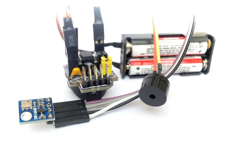
The BMP180TINY is another library for working with the BOSCH BMP180 atmospheric pressure sensor.The source code is available at https://bitbucket.org/tinusaur/bmp180tiny along with some samples.
There is also a Variometer project that uses those libraries to produce audible measurements of the changes in the altitude by measuring the atmospheric pressure and taking into account the temperature. Such tools, or instruments, are often used by paragliders.
Video here:
https://www.youtube.com/watch?v=6JTnYuJGo4w
References
Here are some references to sources that I used while working on this project.
AVR312: Using the USI module as a I2C slave
http://www.atmel.com/Images/doc2560.pdf
C-code driver for TWI slave, with transmit and receive buffers; Compatible with I2C protocol; Interrupt driven, detection and transmission/reception; Wake up from all sleep mode, including Power Down.
TINY USI Interface in I2C mode and the AVR312 Appnote
http://www.aca-vogel.de/TINYUSII2C_AVR312/APN_TINYUSI_I2C.html
What’s wrong with the AVR Appnote?
ATTiny USI I2C Introduction – A powerful, fast, and convenient communication interface for your ATTiny projects!
http://www.instructables.com/id/ATTiny-USI-I2C-The-detailed-in-depth-and-infor/
I2C, it’s a standard that’s been around for around 20 years and has found uses in nearly every corner of the electronics universe. It’s an incredibly useful technology for us microcontroller hobbyists but can seem daunting for new users. This tutorial will solve that problem, first by reviewing what I2C is and how it works, then by going in-depth on how to implement I2C in Atmel’s ATTiny USI (Universal Serial Interface) hardware.
I2C Bus for ATtiny and ATmega
http://www.instructables.com/id/I2C_Bus_for_ATtiny_and_ATmega/
This two wire interface is formally known as the Inter-Integrated Circuit bus, or just the I2C bus and was invented by NXP when it was still Philips Semiconductors. If you’re reading this Instructable then you’ve probably heard of the I2C bus and may even have used it on a PIC or other microcontroller. While conceptually very simple, and supported by hardware resources on the AVRs, software drivers are still necessary to use the I2C bus. Atmel provides Application Notes (see the Resources later in this Instructable), but these are incomplete and don’t show any examples beyond communicating with another AVR device.